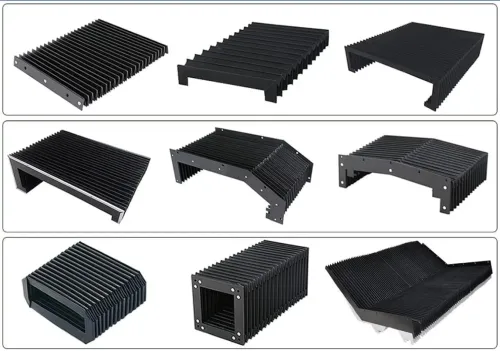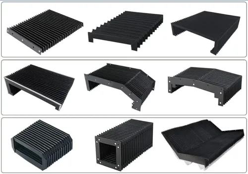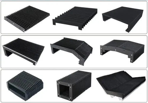

The right cover depends on more than the opening it must close. Match the design to the hazard, motion, available space, access needs and complete machine envelope, then verify the measurements, materials and safety functions before specifying it.
Key takeaways
- Define whether the cover blocks contamination, access, or both.
- Measure the full movement envelope, including folds, bends and service clearances.
- Match cover construction to chips, coolant, heat, oil and motion speed.
- Specify access panels, seals and mounting details before ordering.
Start with the hazard, motion and protection boundary
Define the problem by mapping the hazard, the motion and the protection boundary before comparing machine enclosure cover design options. A cover that only blocks chips and coolant is a contamination shield; a cover that prevents access to moving parts is machine guarding and must withstand foreseeable misuse.
1. Name the hazard: dry chips, fine dust, abrasive swarf, coolant, oil, welding spatter, heat or impact. Record whether material falls, sprays, accumulates in folds or reaches the cover at high velocity.
2. Describe the motion: axis direction, stroke length, speed, acceleration, frequency and available space when the axis is fully retracted and extended. Mark the moving-axis envelope, guideway clearance, bend radius and compression space.
3. Draw the protection boundary. Identify every opening, pinch point and access route, then decide whether the cover protects a guideway only or stops a person reaching hazardous motion. This boundary is the core of your machine cover selection criteria.
4. If a movable cover provides access to the hazard, specify the safety control separately. ISO 14119 covers interlocking-device selection; use guard locking when the machine can still move after access begins. ISO 14120 addresses fixed and movable guard design, construction and foreseeable misuse.
Do not treat an IP54 rating as a complete specification. IEC 60529 tests limited dust ingress and water splashing, not abrasive chips, high-pressure coolant, hot swarf or repeated flexing. A sound design states the hazard, motion, boundary and failure consequence, whether the priority is guideway protection or personnel exclusion.
Match the cover type to travel and available space
Choose the cover by travel direction and the space available for its retracted package: horizontal, vertical, inclined, rotary and telescoping movements create different loading, drainage and clearance problems.
| Movement | Best-fit cover | Space and motion check |
|---|---|---|
| Horizontal | Telescopic steel covers or apron covers | Use steel for hot chips and impact; use slats for long travel when lower mass matters, but protect joints from coolant paths. |
| Vertical | Accordion bellows or roll-up covers | Bellows fold into a short height; roll-up covers need a winding radius and lateral guidance. |
| Inclined | Telescopic steel covers, bellows or apron covers | Provide a drain path so chips and coolant do not settle on folds, ledges or nested sections. |
| Rotary | Accordion bellows or flexible textile covers | Check the bend radius, twist range and rotating-axis envelope; a flat cover will buckle if forced to twist. |
| Telescoping | Telescopic steel covers or sliding panels | Reserve room for nested sections and wipers; misalignment increases friction and can jam the stack. |
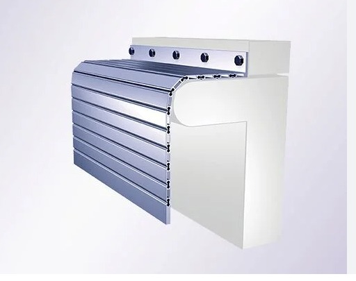
For a long horizontal axis with limited retraction space, compare roll-up covers with apron covers. Roll-up designs occupy the least stored length, but an unsupported span will sag or collapse under chip loads; apron covers handle longer spans yet need a return path that prevents slats lifting or trapping.
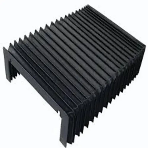
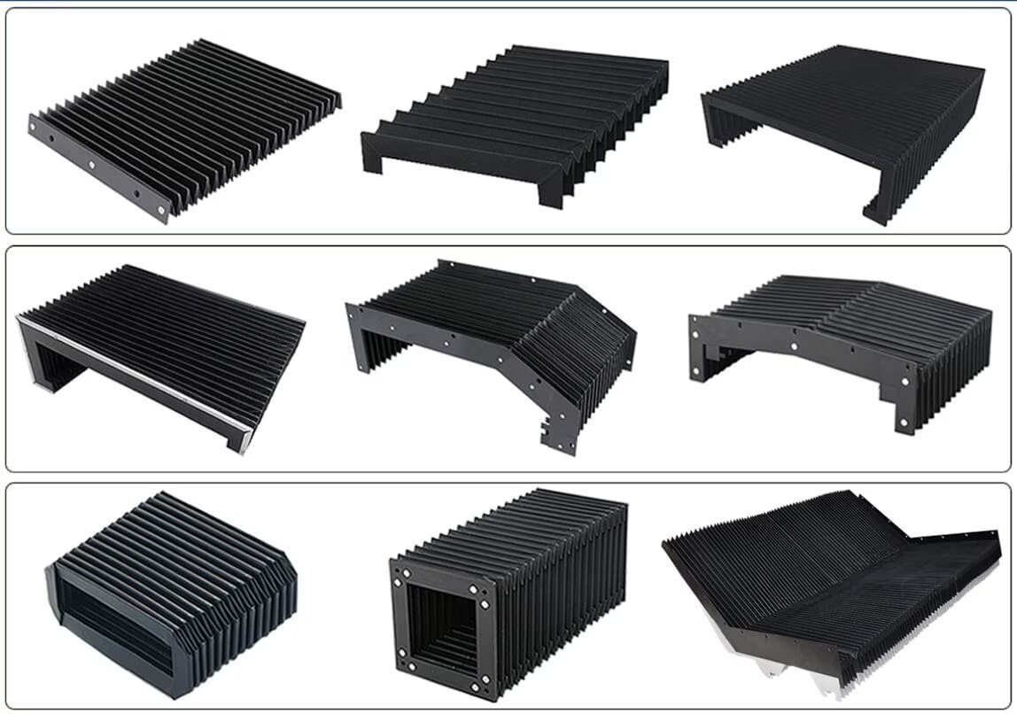
Choose accordion bellows when several axes move together or the cover must compress sharply. Sharp chips puncture folds, while horizontal pleats collect abrasive slurry.
Use telescopic steel covers when rigidity and chip exclusion outweigh moving mass, drive-force demand and drainage maintenance. Measure both extended and closed lengths before accepting any design.
Measure the complete movement envelope before specifying
Measure the complete movement envelope, not just the distance between the machine’s nominal end points. Record the axis position at full retraction, full extension, acceleration, deceleration, tool change and maintenance access; a flexible cover can bulge, a nested cover can shift, and a cable bundle can enter a pinch point.
- Calculate cover stroke calculation from the actual closed and extended positions, including overtravel and mounting clearances.
- Measure folded height and retracted length against nearby tooling, doors, slides and chip conveyors.
- Check width, guideway clearance, mounting faces and every interference point throughout the axis travel.
- Measure the cable carrier’s travel, bend radius, spare length and unsupported span. Keep cables and hoses from rubbing directly on the cover.
- Include thermal expansion, coolant drainage, chip accumulation and the cover’s moving mass in the assessment.
| Measurement | What to record | What goes wrong when it is missed |
|---|---|---|
| Closed and extended length | Cover stroke, end clearances and available compression space | The cover bottoms out, stretches or blocks the axis |
| Folded height | Maximum nested or rolled height | Tool changes and neighbouring axes collide with the retracted cover |
| Extension ratio | Extended length divided by closed length | A design with excessive travel demands more space than the machine provides |
| Unsupported span | Distance without guide or structural support | The cover sags, buckles or carries chip loads poorly |
Repeat the check with the machine at maximum speed and with the cable carrier fully loaded. If a movable cover opens access to a hazard, include the stopping distance and interlock position in the envelope review.
Select materials, seals and access features for service conditions
Choose materials and access features from the actual exposure, not from an IP rating alone. IEC 60529 IP54 covers limited dust ingress and water splashing under test conditions; it does not prove resistance to abrasive swarf, high-pressure coolant, hot chips or repeated flexing.
| Option | Material and construction | Choose it when |
|---|---|---|
| Coated fabric or bellows | Coolant-resistant cover materials, sealed seams and reinforced fold edges | Multi-axis motion, low mass and tight installation space matter |
| Telescopic steel | Formed steel boxes, replaceable wipers and drainage between sections | Hot chips, impact and coolant jets demand rigidity |
| Apron or slat cover | Linked steel strips with controlled joints and supported return paths | Long travel needs lighter protection than nested steel |
| Fixed machine covers | Steel or rigid panels with removable service sections | Contamination control matters more than rapid access |
Use machine cover wipers matched to coolant chemistry, temperature and chip size. A wiper that hardens, swells or curls leaves a direct path to the guideway; specify its replacement interval and provide a drain rather than relying on clearance gaps.
Add reinforcement at mounting points, fold ends, corners and any area struck by chips. Put seams and horizontal ledges out of the chip stream, and slope surfaces so coolant and slurry run away.
- Use captive fasteners for frequent inspections.
- Support removable panels so one person can handle them safely.
- Size access panels around the actual service task, not merely visual inspection.
- Keep hands outside the hazard zone during removal.
- Choose sealed doors only when their hinges, latches and perimeter seals survive the same coolant, heat and swarf exposure.
Turn the specification into a reliable and safe installation
Before machine cover installation, freeze the drawing and verify the cover in its actual end positions. Treat it as one of the ISO 14120 guards when it prevents access to moving parts, not merely as a contamination shield.
A movable access cover needs ISO 14119 interlocking devices, and guard locking is required when the machine can reach the hazard before stopping.
Use this commissioning checklist:
- Cycle the cover through the full stroke at production speed; check for binding, buckling, trapped folds, lifted slats and contact with guides or hard stops.
- Confirm every fastener, bracket and guide is accessible for inspection, and that a loose component cannot enter the machine or create a new pinch point.
- Route cables and hoses independently from the cover. Maintain the manufacturer’s cable bend radius throughout motion, add strain relief at both ends, separate power and signal lines where required, and prevent rubbing against bellows or slats.
- Check carrier fill, unsupported cable weight, torsion and unequal cable lengths. A static routing check will not reveal fatigue caused by repeated minimum-radius bending.
- Test the interlock with the cover open, then attempt foreseeable bypasses; verify that hazardous motion cannot restart until the guard is closed and the control sequence permits it.
Record the test results, stopping time, clearance measurements and fastener torque in the installation file. SCUTES INDIA PRIVATE LIMITED can use those records to resolve whether a failed cover reflects material damage, incorrect routing or an installation error rather than the selected design.
Related products
 | Machine Covers Machine covers are specially designed shields used to protect industrial equipment and machinery from environmental elements. View product → |
 | Roll Up Cover A roll-up cover is a highly durable and flexible protective solution designed to safeguard machinery, equipment, and valuable assets from dust,... View product → |
Frequently asked questions
How do I choose between machine enclosure cover design options?
Start by identifying the hazard, the moving parts and the protection boundary. Then compare travel direction, available space, contamination, temperature and access needs.
What should I measure before specifying a machine cover?
Measure the complete movement envelope, including maximum travel, folded or compressed length, bends, attachment points, clearance from adjacent parts and service access.
Which materials and seals suit a machine enclosure cover?
Choose materials and seals according to the actual chips, coolant, oil, heat, abrasion and movement exposure. Check compatibility rather than selecting by appearance alone.
How can I make a machine cover installation reliable and safe?
Document mounting points, travel limits, fasteners, clearances, access features and inspection requirements. Confirm that the cover cannot create pinch points or restrict machine movement.
Related products
 | TELESCOPIC COVERS A telescopic cover protects guide-way surfaces and components of moving axis of machines. View product → |
 | APRON COVER Effectively engaged in offering a vast collection of outstanding quality products which include Apron Covers. View product → |
 | TELESCOPIC SPRING COVER Telescopic Spring Covers provide protection under extreme conditions. View product → |
 | Laser Machine Bellows Laser Machine Bellows are specialized protective coverings designed to safeguard the vital internal components of laser machines. View product → |