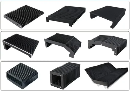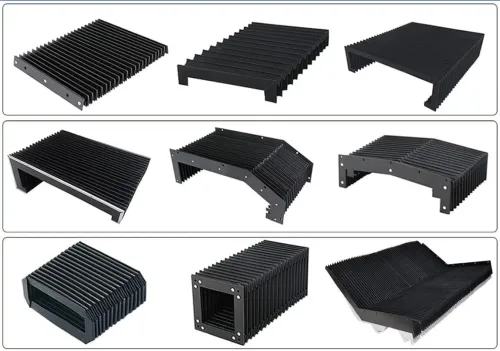

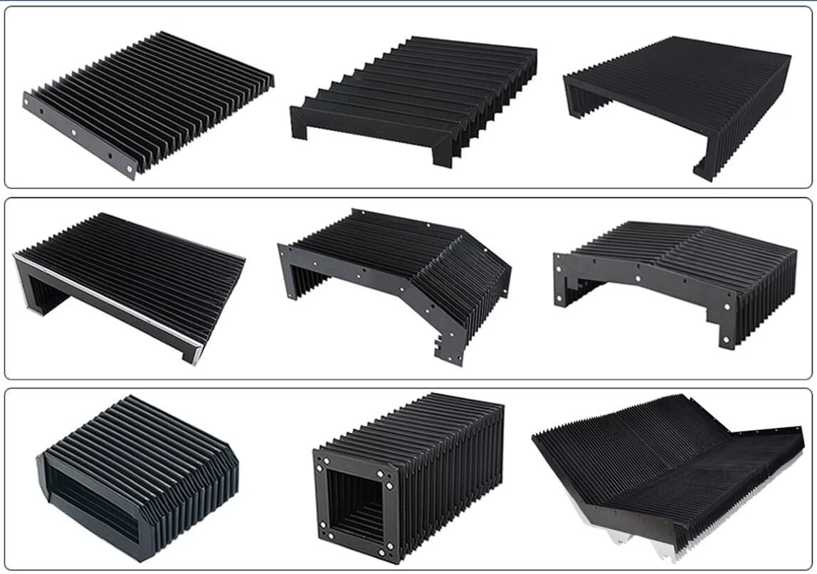
The correct cover depends on how the protected mechanism moves, how tightly it folds, and what enters the machine envelope. By the end, you will be able to match the cover to the geometry, prepare the measurements a supplier needs, and check whether the installed design protects the mechanism without blocking service or safety functions.
Key takeaways
- Match the bellow to movement geometry, not the machine’s trade name.
- Check full stroke, changing width, angles and access clearance before choosing.
- Map every pinch, heat, coolant and chip exposure zone around the mechanism.
- Specify materials, mounting, inspection access and the installed protection function.
How a Flap Bellow Differs from a Scissor Lift Bellow
A flap bellow uses overlapping flexible flaps or slats for predominantly linear travel; a scissor lift bellow encloses a mechanism whose width, angle and opening change as the platform rises. That movement pattern determines the fit more than the product name.
| Factor | Flap bellow | Scissor lift bellow |
|---|---|---|
| Packed height and movement | Usually low packed height; follows a guided axis | Needs space for changing width, angle, opening and folded height |
| Protection | Handles chips and swarf well; overlaps and edges can leave gaps for coolant or dust | Shields the changing hazard zone, but needs clearance around pivots, rollers and drives |
| Service and wear | Easier access; wear concentrates at flaps, slats, folds and mounting edges | Access must follow the mechanism; pivots, rubbing points, folds and attachments need inspection |
| Installation and cost | Simpler mounting; cost follows size, fabric, reinforcement and travel | Guided attachment and interference checks add labour; cost follows geometry, material and custom fabrication |
For a scissor lift bellow comparison, choose a flap design for a mostly linear path where low vertical clearance and chip exposure matter. Choose a scissor-lift enclosure when the platform rises and the mechanism expands, narrows or changes angle; a generic machine-axis cover will not follow that swept envelope.
A flap bellow is not automatically dust-tight or liquid-tight. Expected durability depends on rubbing, compression, coolant, chips and cleaning, not merely on fabric thickness. Neither cover replaces a rigid guard or a separate machinery-safety risk assessment.
Choose by Lift Geometry, Stroke and Available Clearance
For a flap bellow or scissor lift bellow in Pune, use this rule: choose a flap bellow for a mostly guided linear axis with long travel, low packed height and heavy chip or swarf exposure.
Choose a scissor lift bellow in Pune when the hazard zone follows a platform and the mechanism expands, narrows or changes angle during vertical travel.
| Option | Best fit | Main design concern |
|---|---|---|
| Flap bellow | Linear axis, guideway, slide or screw drive | Long extension, compact folded height and chip-resistant overlap |
| Scissor lift bellow | Platform rising around changing linkages | Variable width, angled movement and linkage clearance |
Nominal stroke is insufficient for a lift. The design must show the minimum collapsed opening, maximum raised opening, folded height, diagonal movement, pivot locations and the swept envelope of every scissor arm.
Check these parts at minimum, intermediate and maximum travel:
- Rollers and pivot joints
- Hydraulic cylinders and screw drives
- Hoses and cable carriers
- Limit switches, guards and other safety devices
A generic machine-axis cover is the wrong choice when its fixed width, fold direction or mounting line cannot follow the platform geometry. Forcing it into the gap can cause rubbing, trapped folds, restricted lifting or sudden tearing.
Leave deliberate relief around pivots and service points; sealing every opening can make maintenance impossible and create new interference risks.
Where Flap Bellows Work—and What They Must Withstand
A flap bellow suits CNC guideways, linear slides, screw protection, transfer equipment, inspection systems, exposed positioning axes and other machine-tool travel where the cover follows a defined path. For anyone specifying a flap bellow in pune, the key question is whether movement remains predominantly linear.
Overlapping flaps or slats shed chips and swarf while tolerating repeated sliding contact. Folds and mounting edges can still collect debris, so the design is not automatically dust-tight or liquid-tight.
Specify every hazard the cover must withstand:
- Coolant splash
- Cutting oil
- Abrasive dust
- Heat
- Welding sparks
- Impact
- Repeated compression or extension
Chip exclusion stops swarf reaching a guideway; splash protection limits liquid entry; dust exclusion demands tighter joints and cleaner interfaces; personnel protection requires a guarding assessment. These functions are different, and a machine-protection cover is not automatically a safety-rated barrier.
Reinforced fabric or slats improve abrasion resistance against sharp chips, but they add mass, inertia and packing force. On a high-speed, high-cycle axis, that extra load can increase drive effort, reduce acceleration and accelerate mounting wear. Choose reinforcement from the actual impact and abrasion pattern, not from the word “industrial.”
Measure the Machine and Map the Full Interference Envelope
1. Send the supplier a measured travel schedule, not only the machine’s nominal stroke. State maximum length, minimum or folded length, usable stroke, cover width and height, extension rate, mounting orientation, minimum bend or fold radius, allowable compression, and the mounting-hole pattern with hole diameters and centres. Include travel speed and cycle count if available.
2. Attach a dimensioned drawing showing the machine at minimum and maximum positions, including access panels and every proposed attachment edge. Add clear photographs of the moving mechanism from above, below and both sides.
For a scissor lift, mark changing width, pivot centres, arm paths, rollers, hydraulic cylinder, screw drive, hoses, cable carrier and safety devices.
3. Check the complete travel envelope, not just full rise and full collapse. Trace interference at intermediate heights, where diagonal arm movement can bring a linkage closer to the cover than either end position.
Reserve compressed-length allowance, keep fasteners out of fold lines, remove screw heads and weld beads from rubbing paths, prevent twisting during installation, and fit a positive stop against over-extension.
The drawing must show deliberate relief around pivots, rollers, cylinders, hoses and service points. Do not force a seal around every opening if it creates trapped folds, rubbing or blocked maintenance access.
Confirm that the cover cannot contact the machine throughout travel, because a chemically compatible fabric will still tear against a weld bead or distorted fold.
Specify Materials, Access and the Installed Protection Function
Write the final specification around the installed function, not the word “industrial.” State whether the cover provides chip exclusion, coolant splash protection, dust exclusion, mechanism protection or personnel protection; these are not interchangeable.
- Identify the coolant or cutting-fluid type, oil exposure, abrasive dust, sparks, UV exposure, ambient temperature and cleaning chemicals.
- State flame-retardant or antistatic requirements, travel speed, cycle count and expected maintenance access.
| Material | Best fit | Main caution |
|---|---|---|
| Coated polyester | General dust, chips and moderate splash | Confirm compatibility with the named fluid and temperature |
| Polyurethane-coated fabric | Flexible, abrasion-resistant sliding service | Verify resistance to concentrated oils and cleaners |
| Neoprene-coated fabric | Oil, weather and moderate spark exposure | Check heat limit and chemical compatibility |
| Silicone-coated fabric | High-temperature service and sparks | It may sacrifice abrasion resistance and tear strength |
| PVC-coated fabric | Economical dust and splash shielding | Heat, solvents and repeated folding can shorten life |
A purchase drawing must show minimum and maximum positions, mounting holes, speed, cycle count, photographs and the hazard list. Confirm whether the assembly is a complete enclosure or only a protective cover, then preserve drainage, ventilation, emergency-stop access, inspection points and maintenance openings; sealing them shut can trap coolant and block service.
A search for flap bellow in Pune or scissor lift bellow in Pune is not a specification. SCUTES INDIA PRIVATE LIMITED can use the drawing, travel data, photographs and hazards to evaluate the correct construction and installed clearance.
The supplier must assess the complete moving assembly, including folds and access points, not just a flat material sample.
Related product
 | SCISSOR LIFT BELLOWS Scissor Lift Bellows are one of the broadly demanded stabilizer for which we are considered an acclaimed designed in the market. View product → |
Frequently asked questions
How does a flap bellow differ from a scissor lift bellow?
A flap bellow uses overlapping flexible flaps or slats for predominantly linear travel. A scissor lift bellow encloses a mechanism whose width, angle and opening change as the platform rises.
How should you choose between a flap bellow and a scissor lift bellow?
Compare the lift geometry, total stroke, changing width and available clearance. Choose a design that follows the complete movement envelope without folding into moving parts.
Where do flap bellows work, and what must they withstand?
Flap bellows suit predominantly linear travel where overlapping sections can cover the exposed area. Specify resistance to the machine’s dust, coolant, oil, chips, heat and mechanical contact.
What measurements are needed before specifying a machine bellow?
Record closed and extended dimensions, stroke, mechanism width, operating angles, mounting points, nearby obstructions and access requirements. Map the full interference envelope throughout the lift cycle.