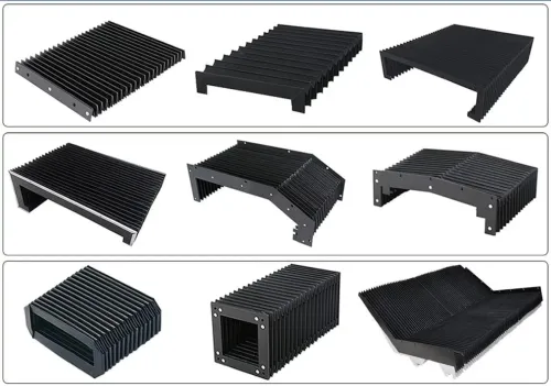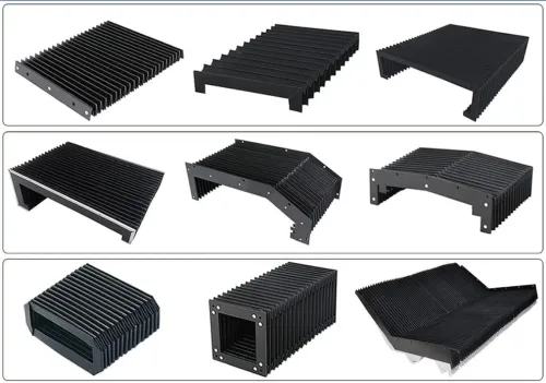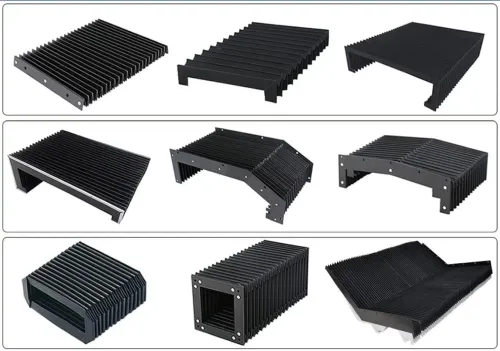


The right cover depends on more than the machine’s open and closed dimensions: movement, clearance, contamination, access and maintenance all change the choice. By the end, you will have a specification you can use to compare cover types, reject unsuitable designs and request a workable prototype.
Key takeaways
- Measure stroke, speed, acceleration and cycle frequency before selecting a cover.
- Match the cover construction to the axis direction and available installation space.
- Specify coolant, oil, chips, heat and chemical exposure—not just dust.
- Include compression, mounting access, inspection and replacement requirements.
Start with movement, clearance and access
Shortlist machine enclosure cover design options from the machine’s movement, available clearance and access pattern—not from the cover’s closed dimensions alone. Measure the full travel stroke, maximum speed, acceleration and cycle frequency, then record the space available above, beside and behind the moving assembly.
A cover that fits at rest can buckle at full acceleration or collide with a nearby axis.
Record these inputs before comparing designs:
- Closed length, open length, cover width, mounting faces and the required bend radius
- Minimum clearance at every position, including cable carriers, tooling and fixtures
- Opening size and how often operators need inspection, loading, cleaning or maintenance access
- Chip form, abrasive swarf, coolant, oil, welding spatter, heat and washdown exposure
- Permitted deflection, target service life and replacement access for wipers, rollers, fasteners and bellows
- Whether anyone could step on the cover or place tooling on it; do not assume it carries either load
| Option | Movement and clearance fit | Access and main trade-off |
|---|---|---|
| Roll-up cover | Suits limited installation depth and flexible travel paths | Fast access, but less rigid and vulnerable to abrasive debris |
| Telescopic steel cover | Handles long linear travel with strong rigidity | Needs stacking clearance; frequent access increases wear at guides and seals |
| Apron cover | Accommodates compact folding and moderate travel | Inspect joints and slats where chips can enter |
| Bellows or spring cover | Fits changing geometry and tight folded height | Flexible protection, but folding zones need clearance and cleaning |
If opening the cover exposes hazardous motion, apply ISO 14120 and ISO 13857 to the complete guard, including openings and reach distances. A quick-release panel can become a frequent-access hazard requiring interlocking and restart analysis.
Match the cover type to the axis
Match the cover to the axis first: use rigid steel for straight, exposed machine-tool ways; use flexible covers when the path bends, tilts or includes three-dimensional movement. The machine enclosure cover design options differ sharply once folded height, sealing and service access matter.
| Option | Flexibility and rigidity | Folded height | Sealing, wear points and maintenance |
|---|---|---|---|
| Roll-up cover | Flexible; moderate rigidity | Small rolled diameter | Fair sealing; edges, roller and wipers wear. Inspect the roll, guides and seals. |
| Telescopic steel cover | Very rigid; straight travel only | Stacked section height | Strong chip and coolant protection. Section overlaps, guides, wipers and rollers need cleaning and adjustment. |
| Apron cover | Flexible across long travel; less rigid than steel | Slat or apron stack | Joints and overlaps admit fine chips and coolant. Clean joints and replace slats, end seals and wipers. |
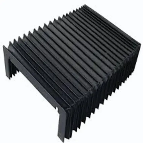
| Bellows | Most flexible; low rigidity | Compressed folded pack | Good enclosure when correctly specified, but folds, seams and fabric abrade or tear. Check material, coating, seams and fold radius. |
| Spring cover | Flexible in one rolling direction; limited lateral stiffness | Very compact coil | Suitable for narrow openings and lighter contamination. Spring edges, guides and wipers are wear points; replacement access matters. |
Choose telescopic steel when hot chips, abrasive debris or high-pressure coolant dominate and the axis is linear. Its mass increases acceleration loads, so section speed and guide friction need checking.
Choose bellows for irregular motion only after checking chip temperature, chemical exposure and fold-crease abrasion. For any option, provide drainage, avoid chip shelves and make wipers, rollers, fasteners and cable-carrier parts replaceable without dismantling the enclosure.
Identify the contamination and chemical load
Choose machine enclosure cover design options by matching every exposed surface to the contamination and chemical load, not by selecting a fabric or IP rating alone. IEC 60529 classifies a complete enclosure in specified dust and water tests; it does not prove resistance to hot chips, coolant chemistry, impact or repeated flexing.
| Hazard | Material and construction choice | Detail to verify |
|---|---|---|
| Dry dust | Coated fabric bellows or roll cover | Closed seams, protected folds and replaceable wipers |
| Abrasive chips | Steel telescopic or slat cover | Hardened wear surfaces, overlapping joints and no chip shelves |
| Hot or incandescent chips | Metal cover or heat-rated protective layer | Temperature limit, spark resistance and drainage away from folds |
| Coolant and oil | Chemically compatible coating, thread and adhesive | Compatibility with the actual fluid, concentration and cleaning agent |
| Welding spatter or sparks | Metal shield or sacrificial outer layer | No exposed fabric folds in the strike zone |
| Heat | Heat-rated fabric, coating, seals and thread | Continuous temperature, peak exposure and cooling time |
| Washdown water | Overlapping joints, end seals and sloped drainage | Hose pressure, spray direction and clean-out access |
Specify the bellows material, coating, thread, seam construction, minimum fold radius and temperature range; “polyester fabric” is not a sufficient specification. Set wiper or brush compression carefully: too much increases drive load and wear, while too little admits chips and coolant. Make them replaceable and adjustable.
Detail every joint and overlap as an ingress path. Provide drainage, avoid blind pockets, and leave access for replacing wipers, stitching panels, rollers and fasteners without dismantling the enclosure. A slat cover is not a sealed enclosure.
Verify travel, compression and installation space
Calculate the cover envelope at both travel limits before selecting among machine enclosure cover design options. Extension length equals the required stroke plus the cover’s compressed length, end attachments and a reserve for installation tolerance; do not use the nominal open dimension alone.
- Compression ratio = compressed length ÷ extended length. Compare this value with the supplier’s stated limit; excessive compression makes bellows fold into themselves and causes a cover to bottom out.
- Set the minimum bend radius from the cover specification. For the cable carrier, use the largest cable or hose’s specified dynamic bend radius, then add separation, strain relief and reserve cable length for the full stroke.
- Check maximum speed, acceleration and cycle frequency against the cover’s permitted section speed. Include moving cover mass, guide friction and roller resistance in the axis load; a heavy telescopic cover can overload the drive during acceleration even when its stroke is correct.
- Reserve clearance around the complete moving envelope: cover deflection, folded or rolled storage, guide hardware, fasteners, coolant drainage and the cable carrier. Test both travel directions, because a carrier forced into the cover space can fatigue cables while the cover itself still moves normally.
Keep the cable route in the design brief rather than adding it after the cover envelope is fixed. Run a slow dry cycle, then a full-speed cycle, and inspect for buckling, section collision, trapped chips, tight cables and contact with nearby machine parts. Include cleaning and replacement access in the measured space.
Turn the choice into a serviceable specification
Turn the choice into a serviceable specification by documenting the loads, drainage, access and evidence required for approval.
1. Define the safety boundary. Check the finished cover and every opening against ISO 14120 and ISO 13857, including reach distances to moving or hot parts. Do not treat the cover as a step, tooling shelf or chip platform unless its structure has been designed and tested for that load.
2. Draw the drainage path. Specify slopes, drain outlets and cleaning access so coolant and chips cannot collect in shelves, folds or blind pockets. An IP rating under IEC 60529 does not prove resistance to hot chips, abrasive swarf, cutting-fluid chemistry or repeated flexing.
3. Make maintenance measurable. State how technicians will replace wipers, guide rollers, fasteners, bellows and cable-carrier elements without dismantling the enclosure. Design cable routing with the cover: reserve full-travel length, use the largest cable’s dynamic bend radius, separate hoses and cables, and provide strain relief at both ends.
4. Ask the supplier for evidence. Request drawings showing mounting interfaces, deflection limits and drain details, plus material compatibility, temperature limits, cycle-life assumptions and test results for the actual chip, coolant and motion profile.
SCUTES INDIA PRIVATE LIMITED can add value by reviewing these interfaces and converting the selected machine enclosure cover design options into a manufacturable prototype with service access and cable routing resolved before release.
Related products
 | Machine Covers Machine covers are specially designed shields used to protect industrial equipment and machinery from environmental elements. View product → |
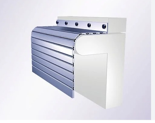
 | Roll Up Cover A roll-up cover is a highly durable and flexible protective solution designed to safeguard machinery, equipment, and valuable assets from dust,... View product → |
Frequently asked questions
What measurements are needed before choosing a machine enclosure cover?
Record full travel stroke, maximum speed, acceleration, cycle frequency, and clearance above, beside and behind the moving assembly.
How do you match a cover design to a machine axis?
Assess the axis direction, travel pattern, available mounting space and required access, then compare cover types suited to that movement.
Which contamination factors affect machine cover selection?
Identify the type and quantity of dust, coolant, oil, chips, heat and chemical exposure the cover must resist.
What should a serviceable cover specification include?
State travel, compression, installation space, mounting details, access requirements, inspection points and replacement considerations.
Related products
 | TELESCOPIC COVERS A telescopic cover protects guide-way surfaces and components of moving axis of machines. View product → |
 | APRON COVER Effectively engaged in offering a vast collection of outstanding quality products which include Apron Covers. View product → |
 | TELESCOPIC SPRING COVER Telescopic Spring Covers provide protection under extreme conditions. View product → |
 | Laser Machine Bellows Laser Machine Bellows are specialized protective coverings designed to safeguard the vital internal components of laser machines. View product → |