
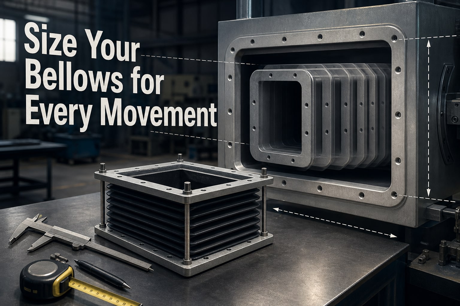
A nominal duct width or diameter is not enough to select a bellows that fits, moves freely, and survives its service life. You will be able to measure the installed envelope, calculate movement and thermal expansion, set compressed and extended lengths, and prepare a specification that a manufacturer can verify.
Key takeaways
- Measure mating openings and the full compressed-to-extended installation envelope.
- Set neutral length between the specified compressed and extended positions.
- Check pressure, airflow, temperature, and nearby obstructions before selecting dimensions.
- Specify movement, lengths, materials, reinforcement, and connection details on the final drawing.
Which dimensions must you measure before calculating duct bellows size?
Measure the complete installed envelope before starting a duct bellows size calculation. Record the mating opening, available face-to-face length in compressed and extended positions, maximum outside space, required movement, and every obstruction near the installation.
- Rectangular duct opening: actual clear width and height, recorded separately
- Round duct opening: actual inside diameter
- Flange or frame: outside dimensions, bolt pattern, frame width, corner radius, and gasket land
- Bellows length: available compressed length and extended length
- External clearance: machine axes, cable carriers, guards, insulation, adjacent structures, and service access
- Attachment: bolts, clamps, welds, retaining rings, or another connection method
Do not substitute nominal duct size, catalogue name, or duct area for these measurements. The duct bellows inside opening must preserve the required free passage after allowing clearance for folds, liners, wire, reinforcing rings, insulation, and installation misalignment.
| Sizing basis | Controlling measurement | Check |
|---|---|---|
| Airflow passage | Clear internal width and height, or actual round diameter | Confirm folds and liners do not intrude into the stream |
| External envelope | Maximum outside width, height, diameter, and length | Check fully compressed and fully extended positions against obstructions |
| Flange or frame | Bolt pattern, frame size, corner radius, and gasket land | Confirm the bellows can attach without fouling or leakage |
For fabric or elastomeric covers, measure space for the minimum bend radius, fold compression, abrasion clearance, and attachment geometry. A cover that fits the opening can still collapse, rub, or trap chips.
For a lined or reinforced bellows, add liner and reinforcement thickness to both the inside-opening calculation and the outside-envelope check. Record the construction before finalising dimensions, because the controlling dimension can change.
The result is a dimensional envelope, not one nominal size. Include vibration, lateral offset, angular movement, and installation clearance when checking the compressed and extended lengths.
How do you calculate the movement and required bellows length?
Calculate the required bellows length from the worst-case motion envelope, not by adding axial, lateral, and angular figures as if they were interchangeable. A duct bellows size calculation must compare the combined motion with the manufacturer’s allowable movement-interaction data.
| Motion component | How to determine it | What to check |
|---|---|---|
| Axial compression or extension | Bellows axial movement from thermal growth, contraction, or machine travel | Compressed and extended limits |
| Lateral offset | Bellows lateral movement between duct centrelines | Allowable lateral movement at the required axial travel |
| Angular deflection | Angle between connected duct sections | Hinge, gimbal, or construction-specific limit |
| Transverse movement | Offset caused by guide misalignment | Guide alignment and combined-motion rating |
For a fixed duct run, estimate thermal expansion duct bellows movement with ΔL = αLΔT. Here, α is the duct material’s coefficient of thermal expansion, L is the restrained length, and ΔT is the actual temperature change.
Use startup, shutdown, cleaning, and upset temperatures, then verify α against the selected material system and the medium direction shown in the layout.
Treat installation tolerance and misalignment as separate load cases. Set required bellows travel at least equal to the worst operating movement plus the specified installation allowance, so the bellows does not start with travel consumed. Check guides, anchors, and supports: they must direct movement into the bellows, not unsupported loads into its folds.
A longer bellows can reduce fold strain; a shorter one saves space but increases local strain and can reduce cycle life. Confirm compressed and extended installed lengths, and provide pressure-thrust restraint where axial movement would otherwise load the ductwork.
How should compressed, neutral, and extended lengths be set?
Set three installed positions for the duct bellows size calculation: compressed, neutral or operating, and fully extended. The compressed bellows length is the shortest installed position; the neutral bellows length, L₀, is the actual operating position; and the extended bellows length is the longest installed position.
Use these calculations:
- Lcompressed = L₀ − compression travel.
- Lextended = L₀ + extension travel.
- Set L₀ from the installation temperature, assembly condition, alignment, and machine position—not from an arbitrary midpoint.
- Keep both calculated positions inside the manufacturer’s specified compression and extension limits.
- Leave mechanical clearance at both ends so folds, wire, liners, and reinforcement cannot bottom against a flange, frame, guard, or moving machine part.
- Check the fully compressed and fully extended outside envelopes against cable carriers, axes, guards, supports, and adjacent ductwork.
Do not permit overextension. It can pull attachment seams, flatten folds, expose reinforcement, or create permanent set. Do not permit bottoming out: the impact transfers load into folds and attachments instead of allowing controlled movement.
For reciprocating equipment, specify movement per cycle, speed, acceleration, dwell time, and expected cycle count. Check a complete full-extension-to-full-compression profile; it gives a more useful fatigue assessment than “continuous duty,” because repeated fold strain can cause failure even when static travel remains within the nominal limit.
Which pressure, airflow, temperature, and construction checks can change the size?
Pressure, airflow, temperature, and construction checks can change a duct bellows size even when the opening and movement are unchanged. Calculate pressure thrust for the pressure thrust bellows with F = pA: use differential pressure p and the bellows effective area A, not an unqualified gauge reading.
State whether the load case includes positive pressure, vacuum, or both, then specify restraints or supports that carry the calculated force.
- Use tie rods when axial movement must be restrained.
- Use hinged or gimbal arrangements when pressure thrust must be controlled while defined angular movement remains available.
- For rectangular ducting, verify effective flow area through the bellows and transition; a projecting liner, abrupt internal step, or fold in the air stream raises pressure loss despite matching flange dimensions.
- For fabric or elastomeric bellows, check fold strain, minimum bend radius, abrasion, chips, chemicals, heat, and collapse.
| Check | What to verify | Sizing consequence |
|---|---|---|
| Pressure and restraint | Differential pressure, effective area, positive and vacuum cases, support load | Changes reinforcement, attachments, and restraint |
| Metal construction | Convolution geometry, material, ply construction, pressure, temperature, spring rate, stability, and fatigue | Requires EJMA bellows design, not a percentage-of-length rule |
| Medium and transients | Actual temperature range and short-duration peaks | May disqualify the selected material |
For metal expansion bellows, these variables are interdependent: larger diameter or taller or additional convolutions can alter thrust, spring rate, stability, and fatigue life. SCUTES INDIA PRIVATE LIMITED can help translate stated load cases into a construction and attachment design, but your measured envelope still determines the final duct bellows size calculation.
Related product
 | Duct Bellows HVAC systems and industrial ducting rely on high-quality duct bellows for durability and performance. View product → |
What should the final duct bellows size specification include?
The final duct bellows specification must describe the complete installed envelope and service duty, not just a catalogue size. Issue it as a duct bellows specification containing:
1. Actual mating opening: rectangular width and height or round diameter; flange or frame dimensions; gasket land; bolt pattern; and maximum outside envelope.
2. Compressed, neutral, and extended lengths; axial, lateral, angular, and transverse movement; bellows installation clearance; and separate installation tolerances for misalignment and travel.
3. Operating pressure or vacuum, temperature range, medium direction, cycle count, cycle speed, required material, liner, insulation, wire, and reinforcement.
4. The support, guide, tie-rod, hinge, or gimbal arrangement, including which parts carry duct loads and which parts permit movement.
5. Leakage limit, inspection method, acceptance criteria, and allowable pressure drop. Verify the internal profile, because a projecting liner, abrupt step, or fold in the airflow can create turbulence and loss.
6. During the duct bellows size calculation, check compressed, neutral, and extended positions. Confirm that folds do not rub, trap chips, foul a cable carrier, collapse into a gap, or transfer unsupported loads to the duct.
7. For machine guarding, derive dimensions from the hazard assessment and verify access, pinch points, detachment, visibility, and containment. Covering an opening alone does not validate a guard; the specification must prove motion, load, airflow, and service-life performance.
Frequently asked questions
Which dimensions must you measure before calculating duct bellows size?
Measure the mating opening, available face-to-face length, maximum outside envelope, required movement, connection dimensions, and nearby obstructions.
How do you calculate the movement and required bellows length?
Define axial, lateral, and angular movement, then set the bellows length to accommodate the full travel without exceeding the selected construction’s movement limits.
How should compressed, neutral, and extended lengths be set?
Set compressed and extended lengths from the installed positions, then place neutral length between them according to the movement required in each direction.
Which checks can change the duct bellows size?
Pressure, airflow velocity, temperature, construction material, reinforcement, vibration, abrasion, and clearance can change the required size and construction.
What should the final duct bellows size specification include?
Include opening dimensions, face-to-face lengths, movement values, pressure, temperature, airflow, materials, reinforcement, connection details, and installation orientation.