
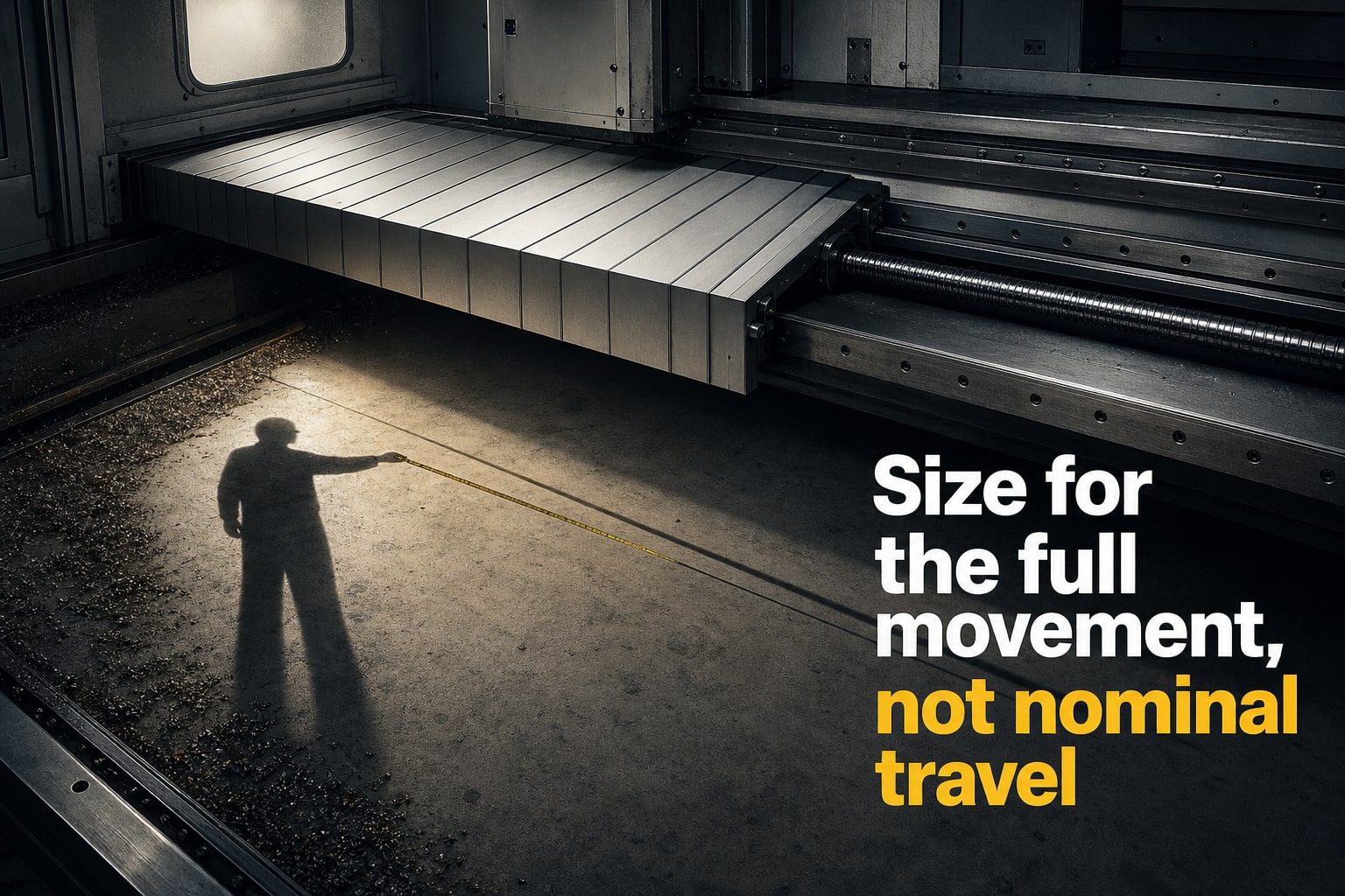
A machine apron cover cannot be specified reliably as width × length because the opening, moving stroke, retracted package and mounting hardware all affect fit. By the end, you will have a measurement checklist and a drawing brief that a manufacturer can use to develop custom machine apron cover dimensions.
Key takeaways
- Measure the full exposed opening, not just nominal axis travel.
- Record maximum extension, minimum retraction and every movement direction.
- Specify bend radius, cross-section and clearance for guides and attachments.
- Send a scaled drawing showing dimensions, movement limits and mounting points.
Start with the opening, not the machine’s nominal travel
The machine apron cover dimensions required for a quotation start with the maximum exposed opening at the guideway or machine gap, not nominal axis travel. Measure opening width and length through the full movement, then add the margin needed to prevent gaps during lateral movement.
Record side seals, wipers, skirts, overlap, and attachment hardware separately; these make the manufactured envelope larger than the visible slat area.
- Protected opening width and length
- Apron total face width, mounting-flange width, and overall width
- Usable covered length, maximum extended length, and fixed-end and moving-end attachment zones
- Minimum retracted or rolled height, maximum stacked or folded height, and available clearance above, below, and beside the cover
- Apron thickness, strip width, and strip overlap
- Mounting-edge dimensions: flange width, hole pattern, hole size, edge offsets, surface orientation, and distance from the mounting face to the first slat or hinge
- Allowable clearances for seals, wipers, skirts, hardware, and lateral movement
Do not combine the attachment zones with the axis stroke. A cover sized only to stroke length can leave the guideway exposed because part of the apron must remain attached and engaged at each end. Submit each field as a separate quotation value rather than one ambiguous width-by-length figure.
Measure the machine through its full movement envelope
Measure the machine apron cover dimensions through the machine’s full movement envelope, not from its home position alone. Mark datums on the fixed mounting face, moving mounting face and guideway centreline, then measure the actual exposed travel between the two extreme positions.
- Record the cover position at full extension, full retraction, axis overtravel, tool-change position, door opening and maintenance access.
- At every position, measure the maximum available space above, below and beside the apron. Check collisions with slides, spindle housings, tool changers, chip conveyors, coolant lines, guards and castings.
- Measure bracket depth, edge offsets, mounting-hole spacing, mounting-face flatness and the distance from each mounting face to the first slat or hinge. Include the protected opening, attachment margins and any space needed for engagement at both ends.
- Give the supplier guide-rail spacing, guide depth, permitted side play, and every step or change in guide elevation. These details control tracking; excessive guidance can bind as the machine heats, while insufficient guidance admits chips and coolant.
- Photograph the installation with a scale visible, but use a dimensioned sketch for manufacture. Show datums, centreline, travel, hole pattern, clearances and retracted stack height.
The controlling measurement is the smallest real clearance anywhere in the envelope, not the nominal clearance at home. Include tolerances, debris space and the apron’s folded or stacked package when checking the retracted end.
Calculate extension, retraction and bend requirements
Calculate extension, retraction and bend requirements as three separate figures: minimum compressed or retracted length, maximum extended length and usable machine travel. Usable travel is the protected movement, not the full apron length.
Calculate maximum extended length as exposed travel plus the fixed attachment zone, moving attachment zone, and the engagement or overlap that must remain at both ends.
Record these machine apron cover dimensions required for quotation:
- Maximum permitted stacked height, retracted depth and side envelope where the apron parks. These limits determine whether the cover can retract without striking guards, tooling or nearby components.
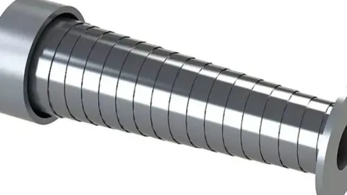
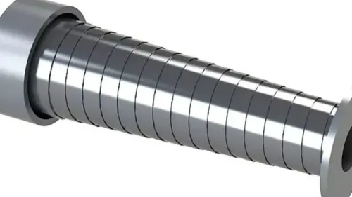
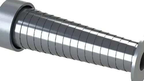
- For a roller-type steel apron, roller or take-up diameter, shaft-centre location, shaft diameter, bearing or bracket envelope, and winding direction. A correct length still fails if the roller cannot fit or winds from the wrong side.
- For every convex or concave transition, the bend radius and transition length. The straight-line distance between mounting points cannot predict binding or hinge loading.
- Slat pitch, slat thickness, hinge construction and slat profile. These control the minimum bend or winding radius and the retracted package.
- For overlapping sections, section count, minimum and maximum section lengths, and overlap per section. Total extended length does not show whether sections remain engaged.
Use these measurements to define custom machine apron cover dimensions, then check clearances throughout extension, retraction and every bend. A package that fits at rest can still foul the machine at mid-stroke.
Specify the cross-section, flexibility and guidance space
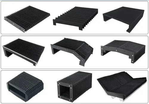
Machine apron cover dimensions must define the cross-section, not only the outside envelope: internal geometry controls stiffness, flexibility, packing and sealing. Wider or thicker aluminium strips add stiffness and weight, while smaller articulation dimensions improve flexibility but reduce rigidity and usable travel.
For the quotation, record each choice separately:
- Aluminium-strip width
- Strip thickness
- Fabric thickness
- Strip overlap
- Closed height
- Side-edge construction, including skirts, folds or reinforced edges
- Minimum bend radius and expected sag over each unsupported span
- Lateral movement the apron must accommodate
- Guide-rail spacing, guide depth, allowable side play, and every step or change in guide elevation
- Clearance from both apron edges to neighbouring machine parts, plus space around seals, wipers, fasteners and brackets
Too little side clearance causes rubbing, buckling and binding when the machine shifts or heats. Too much side play leaves paths for chips and coolant and lets the apron wander out of its guides.
Size the cross-section for the worst-case profile, not the flat opening. Include steps, bends, raised castings, moving cable carriers and coolant lines in their closest positions; a cover that clears only the nominal face can jam against a protrusion or fail to seal during movement.
Ensure the guide depth and side-edge construction retain engagement across the full lateral shift.
Put the dimensions into a manufacturer-ready drawing
Turn custom machine apron cover dimensions into a manufacturer-ready drawing with plan, side and end views. Use clear datums for the protected opening, guideway centreline, fixed and moving mounting faces, travel direction, and the apron’s position relative to the moving axis.
Dimension the drawing with:
- Maximum opening width, total apron width, extended length, usable travel, minimum retracted length, and minimum retracted stack height.
- Roller or bend radius, guide spacing, bracket depth, apron thickness, strip width and overlap, plus the distance from each attachment face to the first slat or hinge.
- Mounting-hole size, hole pitch, edge offsets, flange width, and attachment-face orientation.
- Tolerances for opening width, mounting-hole locations, mounting-face flatness, side clearance, and the maximum permitted package envelope at full extension and retraction.
Add the machine model, axis name, travel direction, operating temperature, chip type, coolant condition, and photographs taken with a scale. Show collisions above, below and beside the cover, including the spindle housing, tool changer, enclosure and chip conveyor.
| Standard design | Uses stated width and travel | Fits when mounting faces, guidance and retraction space match |
|---|---|---|
| Custom design | Uses measured openings, envelopes and hole patterns | Needed when castings, offsets or limited stack space differ |
SCUTES INDIA PRIVATE LIMITED can use this information to assess fit, guidance, retraction space and attachment details instead of relying on a model number. Ask for a dimensioned approval drawing before production.
Related products
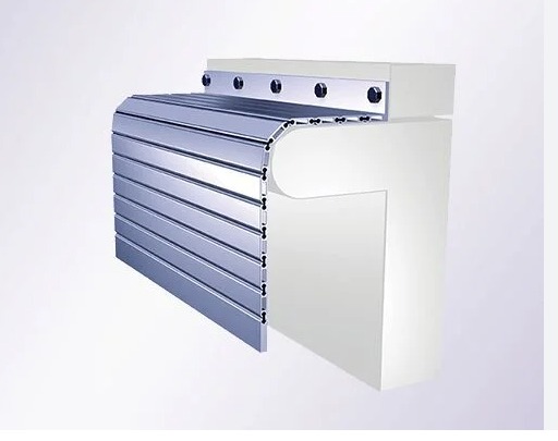 | APRON COVER Effectively engaged in offering a vast collection of outstanding quality products which include Apron Covers. View product → |
 | Machine Covers Machine covers are specially designed shields used to protect industrial equipment and machinery from environmental elements. View product → |
Frequently asked questions
What should you measure first for machine apron cover dimensions?
Measure the maximum exposed opening at the guideway or machine gap through the machine’s full movement envelope. Include opening width, opening length and lateral movement that could create gaps.
How do you calculate extension and retraction requirements?
Record the cover’s maximum required extension and minimum retracted length at each end of travel. Include overlap or margin needed to keep the opening covered during movement.
Which cross-section and flexibility details belong in the specification?
State the required cover width, height, thickness, bend radius, flexibility and space for guides, rollers, fasteners and adjacent machine parts.
What should a manufacturer-ready apron cover drawing show?
Provide a scaled drawing with overall dimensions, opening size, movement envelope, extension and retraction limits, bend requirements, mounting points, clearances and attachment details.