
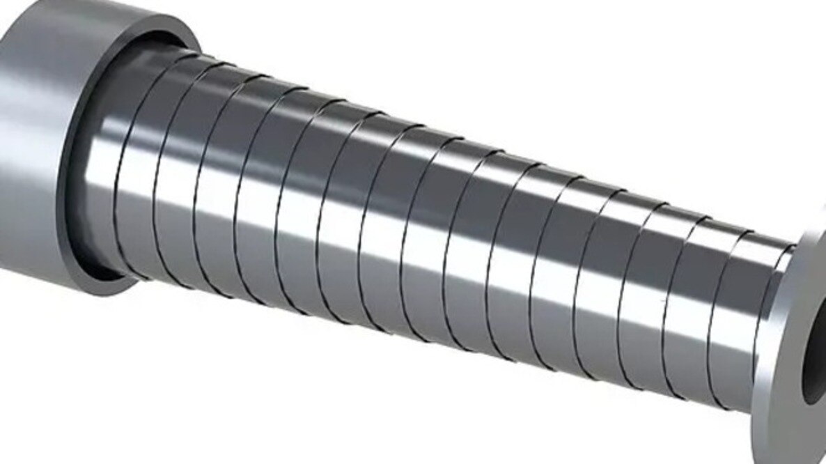
A cover that fits the machine at full stroke can still rub, jam, sag or become a hazard during acceleration, reversal and cleaning. You will be able to map the motion envelope, select a cover architecture and define measurable acceptance tests before asking a manufacturer to build it.
Key takeaways
- Map full travel, overtravel, contamination, temperature, and maintenance clearance.
- Calculate compressed length, extended length, folds, mounting space, and guideway clearance.
- Choose cover architecture and materials for chips, coolant, heat, speed, and acceleration.
- Validate safety, cable clearance, sealing, access, and service life before approval.
Start with the complete motion and contamination envelope
Machine cover design for moving parts starts with the complete motion and contamination envelope, not the nominal stroke. Record travel, overtravel, acceleration, reversal, deflection, orientation, temperature, chip and coolant direction, cable-carrier travel, compressed and extended cover length, mounting hardware, guideway clearances, and the space needed to clean and maintain the axis.
A cover that clears both endpoints can still foul during acceleration.
Define the duty with these measurements:
- Maximum speed, acceleration, reversal frequency and operating hours per shift.
- Travel length, guideway width and height, mounting points, interference zones and allowable folded length.
- Chip size, coolant volume, abrasive dust, heat sources and cleaning method.
- Cable-carrier movement, nearby springs, sensors, hoses and access panels.
Support linear guides, telescopic sections and bellows frames independently. Do not make the cover carry guide loads; misalignment shows up as asymmetric folding, edge wear, higher servo load or jammed sections.
Choose the architecture against the actual exposure and motion profile:
| Cover architecture | Best fit | Main design concern |
|---|---|---|
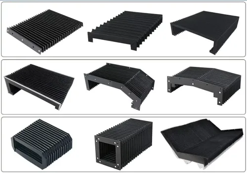
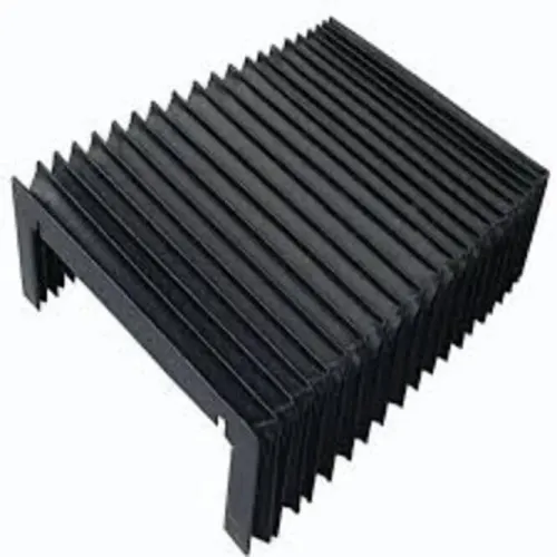
| Bellows | Flexible enclosure of linear axes | Folding clearance and contamination-resistant seams |
| Telescopic steel | Hot, sharp chips and directed coolant | Section alignment, mass and packed length |
| Roll-up | Low packed length and open access | Sag, winding control and edge guidance |
Treat moving edges, overlaps, exposed springs and attachment points as shear, crush and entanglement hazards. If the cover is a safety guard, specify retention, strength, access and interlocking separately under ISO 14120; an ordinary flexible cover is not automatically a validated guard.
Measure the machine and calculate the packed dimensions
Good machine cover design for moving parts starts by converting the axis travel and available installation space into four dimensions: extended length, packed length, width and height. Measure the real motion, including overtravel, reversal position, acceleration-induced deflection and cable-carrier movement; a cover that clears both end positions can still foul during a fast direction change.
Record these dimensions on the machine, not from a drawing alone:
- Axis travel, overtravel and the distance available at each end
- Guideway width, moving-slide width and the highest nearby obstruction
- Mounting-face locations, bolt access and the overlap needed at fixed and moving ends
- Cleaning and maintenance clearance around the cover
- Cable-carrier travel, hose loops and any zone that can enter the cover’s path
Calculate the required usable cover travel as axis travel plus overtravel and a clearance allowance for deflection. Then select the packed length so the extended length minus packed length meets that requirement; do not treat the nominal stroke as the cover’s expansion.
The packed length also includes end frames, mounting flanges and the folded or nested sections. Check the fold pitch or telescopic section depth against the manufacturer’s compression limit, because bottoming out creates rubbing, fabric damage or jamming. Verify the cover at full extension, full compression and during acceleration.
Record speed, acceleration, reversal frequency, orientation, coolant exposure and temperature for the duty-cycle review; a short stroke with constant reversals can be harder on the cover than a long stroke used occasionally.
Match the cover architecture and materials to the duty
In machine cover design for moving parts, choose the architecture from the contaminant, motion profile and available space—not from stroke alone. Match fabric, steel, seals and guidance to speed, acceleration, reversal frequency, temperature, coolant and chip load.
| Option | Best fit | Material and design watchpoint |
|---|---|---|
| Bellows | Flexible linear axes needing enclosed protection | Use coated fabric, polymer or heat-resistant fabric; support frames independently and prevent sharp folds |
| Telescopic steel | Hot, sharp chips and directed, high-volume coolant | Use formed steel sections with positive guides, seals and controlled overlap; chips between sections can cause jamming |
| Roll-up | Long travel where low packed length matters | Control sag, winding tension and edge guidance; a loose curtain can rub, buckle or expose the guideway |
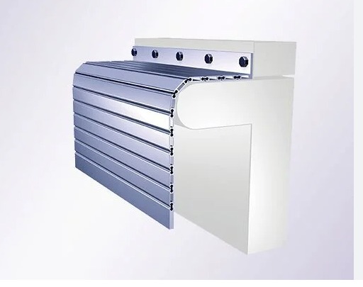
| Apron | Broad surfaces, moderate contamination and access-friendly layouts | Use overlapping steel or polymer slats; protect joints from chip packing and keep the apron supported |
| Spring cover | Compact protection for short or moderate travel | Select spring steel and winding hardware for the cycle rate; exposed springs create pinch and entanglement points |
Keep the cover independent of the machine guides. Misalignment transfers force into the cover, producing asymmetric bellows folds, edge wear, higher servo load or jammed telescopic sections.
Test the selected cover through the real duty cycle, including reversal frequency, orientation, vibration, temperature and contamination. Assess moving edges, overlaps, springs and attachment points as shear and crush hazards; chip protection does not replace machine guarding.
Detail the folds, seals, guidance and cable clearances
Folds, seals, guidance and cable clearances determine whether machine cover design for moving parts survives its duty. Shape horizontal panels with a slope toward a discharge edge, scraper or cleaning opening; flat ledges and fold valleys collect chips that abrade fabric and block retraction.
| Detail | Specify | Failure prevented |
|---|---|---|
| Fold valleys | Smooth, open geometry with no chip-catching pockets | Packed chips, fold abrasion and incomplete closing |
| End seals | Replaceable wipers or labyrinth seals matched to coolant direction | Coolant and chips reaching guides, ballscrews or bearings |
| Guidance | Captive guides, rollers or side rails that prevent lateral drift | Telescoping sections skewing, rubbing or jamming |
Keep seals flexible across the full stroke and protect their edges from direct chip impact. Check every overlap for a pinch or shear point; a cover that blocks contamination is not automatically a machine guard.
- Keep the cable carrier outside the cover’s moving envelope, including sag, reversal movement and maintenance access. Set clearance from the largest cable or hose bend, not its straight-line diameter.
- Fill the carrier so cables do not cross, twist or press against separators. Separate abrasive or incompatible lines, support heavy hoses, and use strain relief so connectors carry no tensile load.
- Leave space for coolant drainage and cleaning tools around mounting flanges. Specify replacement triggers before commissioning: torn fabric, flattened folds, leaking seals, bent sections, abnormal drive load, jacket wear or damaged separators.
Validate safety, performance and maintainability before approval
A machine cover design for moving parts is ready for production only after it passes the machine’s real motion, contamination and maintenance conditions. Test the finished assembly, including frames, fasteners, seals, cable carriers and access panels—not a material coupon or an isolated cover section.
1. Run the cover through the full duty cycle: maximum stroke, speed, acceleration, reversals, orientation and planned cycle frequency. Include overtravel and powered stops. Watch for asymmetric folding, rubbing, jamming, guide interference, increased servo load, loose fasteners and damage at attachment points.
2. Repeat the test with the actual coolant, chips, dust, oil and temperature range. A cover that survives a clean bench test can split, seize or retain abrasive debris in production.
3. Inspect every moving edge, overlap, spring, frame and mounting point for shear, crush and entanglement hazards. If the cover is intended as a safety guard, verify strength, retention, access control and interlocking separately against ISO 14120 and the machine’s safeguarding requirements. Blocking chips does not make a flexible cover a safety device.
4. Perform the cleaning and replacement tasks using normal tools. Confirm that operators can reach inspection points, remove trapped debris, replace wear parts and reconnect cables without entering a hazardous zone.
Approve the design only when test records show no interference, unacceptable wear, exposure or maintenance obstruction, and the machine’s guide loads remain independent of the cover. SCUTES INDIA PRIVATE LIMITED can use these acceptance checks when choosing between a bellows, roll-up or telescopic arrangement for a particular axis.
Related products
 | Machine Covers Machine covers are specially designed shields used to protect industrial equipment and machinery from environmental elements. View product → |
 | Roll Up Cover A roll-up cover is a highly durable and flexible protective solution designed to safeguard machinery, equipment, and valuable assets from dust,... View product → |
Frequently asked questions
What must you record before designing a machine cover for moving parts?
Record travel, overtravel, acceleration, reversal, deflection, orientation, temperature, chip and coolant direction, cable-carrier travel, packed and extended cover length, mounting hardware, guideway clearances, and cleaning and maintenance space.
How do you calculate the packed dimensions of a machine cover?
Measure the full axis envelope, then calculate the cover’s compressed length, extended length, fold or segment count, mounting allowance, guideway clearance, and space occupied by hardware throughout the motion.
How do you choose the right machine-cover architecture and material?
Match the architecture and material to the duty: contamination type, chip size, coolant or oil exposure, temperature, travel speed, acceleration, orientation, deflection, and required access for maintenance.
What details must be checked around folds, seals, guides, and cables?
Check fold geometry, seal contact, guide alignment, mounting transitions, cable-carrier travel, bend radius, cable clearance, and interference at every position from fully compressed to fully extended.
How should you validate a machine cover before approval?
Test the complete motion for interference, safe operation, sealing, repeated travel, cable clearance, cleaning access, inspection access, and maintainability under the expected contamination and temperature conditions.
Related products
 | TELESCOPIC COVERS A telescopic cover protects guide-way surfaces and components of moving axis of machines. View product → |
 | TELESCOPIC SPRING COVER Telescopic Spring Covers provide protection under extreme conditions. View product → |
 | Laser Machine Bellows Laser Machine Bellows are specialized protective coverings designed to safeguard the vital internal components of laser machines. View product → |
 | APRON COVER Effectively engaged in offering a vast collection of outstanding quality products which include Apron Covers. View product → |